|
By TimV - 11 Years Ago
|
Hi:
I have searched the forum for Perform and Perform Menu. I have certainly seen animation clips for various actors that are linked to the Perform menu which is available by right clicking the actor / avatar.
What I have not found (including the manual) is a way to create / attach the framework to my aircraft (My ongoing V22 animation). Now that I have the propellers rotating, I have many more parts to animate and it would be nice to be able to click select them from a menu, at least to get them operational and tested (what is a realistic time to lift the gear and close the doors - which I can get from actual video footage). I would then like to be able to save various clips so that when I try to put a path and timeline in place, I could drop the clip on the timeline.
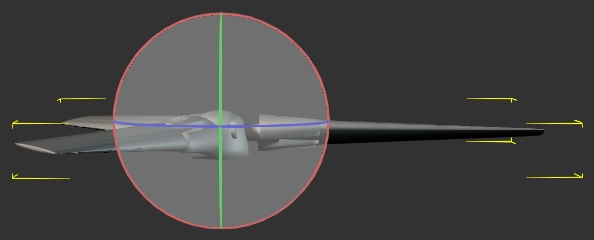
To animate a whole timeline, I can envision a takeoff where I would close the doors, start the props from stopped, one motor at a time and then bring them up to speed (the 50 maximum on the force option is not fast enough), and lift the aircraft off the ground. Next would be to retract the gear and close the bays, and since this is a V22, the engines would rotate from vertical lift to horizontal thrust and the aircraft would depart.
I'd like to get all the different parts working properly with the aircraft sitting in front of me.
If someone can head me in the right direction to get started, I would really appreciate it.
Thanks
Tim
|
|
By Cricky - 11 Years Ago
|
http://manual.reallusion.com/iClone_6/ENU/Pro_6.0/09_Animation_Timeline_Editing/Collect_Clip_Track.htm
Learn this and the rest will come to you. If nothing else, attach all your separately collected animation parts to a "DUMMY" and use it as your ROOT of the hierarchy.
|
|
By primaveranz - 11 Years Ago
|
Watch Mark's video tute on this very topic here:- https://www.youtube.com/watch?v=SGtGZ82PM3o
Mark, Warlord and Rampa especially have done loads of videos covering just about everything there is to know in iClone. I'd highly recommend them.
|
|
By TimV - 11 Years Ago
|
Thanks very much!!
Exactly what I was looking for.
Tim
|
|
By TimV - 11 Years Ago
|
Hi:
No, I didn't give up. I am looking for suggestions on dealing with physics, and rotational constraints specifically. I can't get what I am doing to match what is happening in the tutorials. No doubt it is me.
Before getting to this point, I took my V22 model and I manually key framed ALL of the animation. It was a lot of work and it took me a long time, because I have never really done it before. I did the main landing gear from 0 to -80, the nose gear from 0 to +90. I did my propeller assemblies, one with positive rotation and one with negative. They are in sync with each other. I stayed with increments of 40 degrees as the max rotation per step as it looks more realistic than 60 degree steps. I did my motors from 0 (straight up) to -90 (pointed forward). I used the same pivot point between the props and the motors so that the props rotate correctly even while the motors are rotating.
Now I am trying to do the animation with the physics window instead of keyframing it manually.
Every time I try to add a rotational constraint through the physics window, I end up getting something at least 90 degrees out along one axis. Maybe it's to do with x,y,z directions from the original modeling software or something I'm not setting into or out of one of the packages. In this case it is Blender to 3dxchange to IClone6.
What I have been doing works, but it is not the right way I'm sure. I am pulling the constraint directly out of the Add Constraint window and manually adding it to the object that I wish to animate. I line up my Pivot Point between the hinge and the object and apply a force along the axis I want. That's not too bad when the alignment is on a specific axis. I then set my force and the constraint angles. In my timeline, I do have my animation in the animation line of the object which was the goal.
Where I am looking for help is on the wing assembly for example. The wing leading and trailing edges are on an angle, (so not 90 degrees from the body) I have tried to set the hinge in the center of the object (from left to right along the flap or airelon for example) and angled to match the angle of the wing. I line up my pivot points between the hinge and the object, but it is brutal trying to find the right place and the right angles. My object invariably is out of position with the wing for alignment. Either it's out with one end too high and the other too low, or the left end is back too far and the right end forward too far, or any number of other misfortunes. I can't seem to get it to stay in line with the trailing edge of the wing.
In short, there must be a better way that isn't mostly guessing.
best,
Tim
|
|
By TimV - 11 Years Ago
|
Ok
There is a big difference between moving an object by it's pivot point, or just moving it especially if you click on the option to move the pivot point.
I had set up all my pivot points in 3dxchange, so when I double clicked in the content folder, they came in where they were supposed to relative to the object.
I'm not sure my pivot point moved with the object when I moved the object, but if I moved the object by moving the pivot point, they stayed together. Am I getting in trouble with local vs global space again?
I got things lined up by selecting the option to move the pivot point, With that selection active, I moved my object where it was supposed to be. I then reset my pivot point to what it had been before I moved the object.
Maybe I'm nuts, or just confused by everything I was moving around, but it took me hours to get things lined up. Everything was perfect to look at, but when I pushed run on the animation, part of my motor assembly flipped 90 degrees. I set the option to adjust the pivot point and then rotated the object to where it was supposed to be, even though the object was linked to another object in the assembly that did not flip out on me.
Any wisdom welcome.
Thanks,
Tim
|
|
By Rampa - 11 Years Ago
|
Each part that rotates needs it's pivot at its point of rotation.
Your propeller pivot should be in the center of your propeller. Your engine pivot should be in the center of your engine. Etc. Landing gear needs its pivot at its top where it rotates to tuck into the plane. Think about the actual mechanical device, and assemble it as such.
For parts that are attached to something else, and do not rotate themselves, it doesn't really matter where their pivot is.
Here is the iClone 5 pivot manual page. It is the same in iClone 6, just darker gray. :)
https://www.reallusion.com/iclone/help/iclone5/PRO/11_Props/Prop/Pivot_of_Prop.htm
|
|
By TimV - 11 Years Ago
|
@rampa
Hello and thank you for your input. I had reviewed the manual page several times for information on pivot points,
Of particular note today is the note below which I had not seen. This is the key to my issues. Thank you
Tim
| Note: | - Please refer to the World or Local Axis section for more information on the reason that you need to rotate the pivot orientation.
|
|
|
By TimV - 11 Years Ago
|
Observations
In 3DXchange6, I have exported only the items associated with the right hand propeller assembly
I selected each of them and created a sub prop.
I could not use the editor to view or modify the pivot point.
I selected the option for Z is up (instead of Y)
Doubleclicked the item in IClone6 Content to bring it up. World view shows Z is up. Local view is the same looking at the rotation ring relative to the axis map.
Ok, I had another picture in here showing the pivot point at 0,0,0 when the object came it. Here I have aligned the pivot point to be
156,-704,274
I have added a hinge. The hinge is located at 156,-704,294. Rotation is set as Y= -90.
In limits, Axis is set to free. Force has been activated at 1 unit.
Now I hit Play
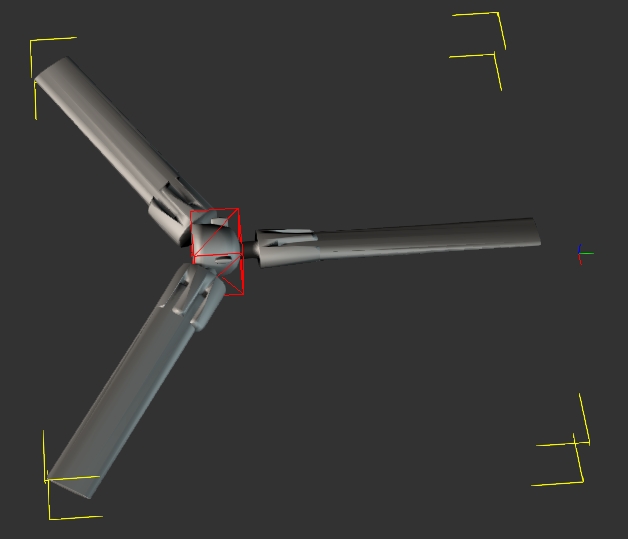
Why did the spinner rotate 90 degrees and how do I fix this to avoid it in the future? Everything was aligned around the same planes!
Is the spinner acting on the Y= -90 that I set for rotation? That is there so that the spinner rotates around the Y axis.
Is this a bug in the software?
Please help
Tim
|
|
By TimV - 11 Years Ago
|
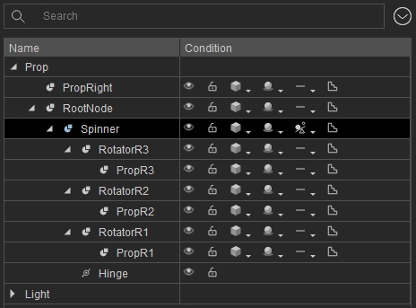
This might be helpful. I'm not sure, but the spinner is the main object to which everything is attached in order.
|
|
By Rampa - 11 Years Ago
|
I've got an idea what might be going on, as it looks like everything is centered properly. You are probably correct with your global/local space observation.
If you look closely at the gizmo icons, you'll notice they have a drop down menu. This menu lets you set them to global or local. Try setting them to local. My theory is that the pivot of the object is indeed rotated at 90 degrees from.
For a "kludge" fix, you could also just rotate your hinge on a different axis. But would go into the pivot edit box and just rotate it so it's axii are pointing the right directions, using the local space rotation gizmo.
|
|
By TimV - 11 Years Ago
|
@rampa
Thanks!!! I did notice the down arrows, but didn't try them. I'm liking this idea.
I will let you know.
Tim
|
|
By Rampa - 11 Years Ago
|
Doh!
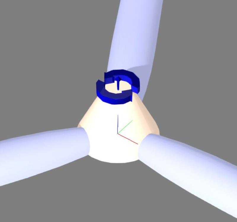
Just realized that your hinge may not be in line with your propeller axis. That would cause this issue. Make sure the hinge is sitting flat on the propeller. The hinge rotation takes priority over the gizmo orientation. Notice that the hinge has a little arrow that indicates its axis.
|
|
By TimV - 11 Years Ago
|
@rampa
Hi.
I set everything to local. It still happens. Everything to global.
Ok. This isn't right. It changes per click on the drop down, not by the item selected. I will set it all to world and then reset my pivot points.
the software crashed, no warning. I can't reload the file so I will have to redo it.
What I did see though, was that when I set it to local, it was lined up. When I set it to world, my pivot points were all over the map. When I redo it, I will set it all to local.
Reloaded the prop assembly. Checked each item in my list and the pivot point in world view is 0,0,0 for everything. No rotation numbers at all (in the transform data of modify)
Set the gizmo to local. transform data shows everything in the assembly at 0,0,0.
I keyed my location data into the transform section and moved all of the items to where I want them.
When I look at it now, the location data is entered as the pivot point, but the actual pivot point is showing as 0,0,0
set gizmo to local, set all my pivot points to the location I want 156,-704,-45.6. Pivot point is lined up with objects in assembly.
added hinge, set location of hinge to 156,-704,-45.6 Rotate in the transform section has Y=-90 for rotation
I give up!!!! I put a force of .1, activated and hit play.
Here is what I got!!
My spinner is out by 90, and this time my prop rotators are in a perfect group, as well as my props in yet another group, equally spaced away from the spiner.
|
|
By Rampa - 11 Years Ago
|
You might want to upload the project, as I am out of ideas without playing with it myself. I'd be glad to have a look at it.
|
|
By TimV - 11 Years Ago
|
Hi
Went back to Hexagon. created a new prop of a group which is the items in the prop assembly. saved it as an obj file.
loaded it in 3DXChange
sent it to iclone
set the linear and orbital gizmos both to local. set the pivot point on all of the objects.
added the hinge and set the pivot point.
activated and set a force.
propeller works perfectly. everything is lined up and nothing switched positions. i wish i knew what was different.
I'm thinking that since the arrow is so tiny on the hinge, maybe it was inverted
|
|
By TimV - 11 Years Ago
|
Hi:
I now have two working prop assemblies which are both animated properly. I'm now at the point that I was most concerned about. I need to keep the props at the end of the motor while the motor rotates through 90 degrees (vertical lift to forward thrust)
I attached the spinner to the motor and tried selecting position and rotation inside the ... at the right. The motor rotates, but the props do not follow
I attached a 2nd hinge lower than the first hinge and set it to hand the rotation (thinking I would attach the motor to it later), but the two hinges fight to a draw.
I'll see if I can find a tutorial. It can't be this difficult
Tim
|
|
By Rampa - 11 Years Ago
|
OK, I do know what is going on with the props not following. The motors need physics enabled, and set to kinematic. Still just the one hinge on the prop targeted to the motor. You will see a red box for the hinge, and a green box for the target.
The kinematic setting does not respond to physics, and so can be animated. You still need to attach everything, even if it's held by the physics, so you can move your prop around with it in one piece. The physics is only active during playback.
|
|
By primaveranz - 11 Years Ago
|
Target the propeller's hinge constraint to the motor body rather than "world" and it works.
See this vid:- http://primaveranz.com/machinima/wp-content/uploads/2015/05/prop.mp4
|
|
By TimV - 11 Years Ago
|
@rampa, @primaveranz
Thank you both, and yes, primaveranz, I am trying to do exactly what it is in your video.
I have tried everything that I can think of to change the constraint target to be the motor. It remains at World. I am convinced that this parameter cannot be changed manually. Every attempt with the hinge highlighted to "pick target" and then select motorL from my scene list drops me into the material editor. Do I have to have something specific selected in my scene?
I have attached the iproject, well, tried to. I'm getting a message that I'm not allowed to attached that file type. (iproject)
How can I get this to you so you can see what is going on and try to help me straighten it out?
my email is available on request. maybe i can reply and attach the file.
Thanks,
Tim
edited to remove email address
|
|
By Rampa - 11 Years Ago
|
Make sure the motors are set to physics activated and kinematic.
I just emailed too.
|
|
By Rampa - 11 Years Ago
|
Not sure why it was not letting you set the hinge target. The motor was kinematic. All I had to do was attach it. I did check with the physics disabled on the motor, just to see if I was dreaming, and it would not target. So it really must have physics enabled.
Chock that one up to Mr. Murphy, I guess! ;)
|
|
By primaveranz - 11 Years Ago
|
|
TimV (5/31/2015)
@rampa, @primaveranz
I have tried everything that I can think of to change the constraint target to be the motor. It remains at World. I am convinced that this parameter cannot be changed manually. Every attempt with the hinge highlighted to "pick target" and then select motorL from my scene list drops me into the material editor. Do I have to have something specific selected in my scene?
I have found that selection process a bit flaky at times, but I have no idea why it refuses to work at all for you. I do remember from other softwares over the years that sometimes weird non-interaction with menus can be caused by Video drivers being out of date, graphics cards not being powerful enough or sometimes even anti-virus plugins doing weird things. It is a shame for you, as like I mentioned before, I have found the potential to animate and even build props inside iClone a massive time-saver over external tools.
|
|
By TimV - 11 Years Ago
|
Hi
Thank you both. I have found that I am more inclined to enter data than to move things with the mouse. That means that I will click on the item in the list rather than it's visual in the main window. Here is what I can say for absolute certain. If you want to select a target for the bottom half of the hinge, you must select the object in the edit screen. If you select the object in the Scene list (which is what I did 100% of the time), it will not pick it up as the target.
Another bit of interesting observation is that it is possible to reorient an object while keeping the pivot point consistent. I the cases where I was reporting that an object was flipping 90 degrees out of phase when I hit run, you can look at the assembly and it looks perfect, you can check the pivot points and have them all line up ahead of time.
You can then hit run, and an item in your assembly can flip 90 degrees out of sync with the other objects even though they are all attached. When you hit stop, the item will still be 90 degrees out. You have to "Detach" all of the objects that are attached to the object that flipped, then rotate the object using the rotate gizmo, and then reattach the items to the object. Now when you hit play, the item will not flip since it is properly aligned. When you recheck your pivot points and transform information it will say exactly what it did when it was flipping. It's like there's a hidden panel.
I am extremely grateful to rampa who took my file and made it work. With that as a guide, I have been working all afternoon on the other engine assembly. I am keenly aware of all settings being local. I am trying to match every single property and value between the two motors and I am finding things that don't match or change after I have set them. At the moment, my left motor is at a different height, and the left prop is as well. Looking at x,y and z values shows that they are the same except for Y which is negative on the starboard side of the aircraft. I can opt to edit the pivot point, and it will let me. I set the pivot point where it should be, and it moves, but the object does not. I then move the object by hand or with the values in the transform section. Once I get it lined up, I then have to move the pivot point again. The thing is, that the information that I put in the pivot point and then the transform is the same data that I had originally put in both locations, so something is changing. I'm not sure if it's the hinge data, or the object data, or why it is changing what I set,
In theory, I should be able to put the exact data that is in the motor/propeller assembly that rampa did, into my other motor assembly, use a negative of the Y value to put it on the other end of the wing and that should be it. Well kids, it don't work like that!!
rampa, if you want to look at it with both motors, let me know and I will send it over. There should be a logical explanation.
thanks
Tim
|
|
By TimV - 11 Years Ago
|
Further information that just makes sense now. When the model was created, I'm sure they took the finished parts from one motor and mirrored them across. Since the motor is a mirror image of itself, once it gets broken apart in IClone, I then have to feed it coordinates to mirror the other engine. Ie it needs to rotate 180 along it's z axis. It wants to be 90 degrees along the x axis which I don't understand, but it is oriented correctly when I look at it and when I hit run. It is still not rotating from straight up to pointing forward, I need to reverse the force to be negative, but there is no force setting that I can see. I tried reversing the 90 to -90 that is set in the constraint on the left engine, but it was ignored.
This is driving me nuts!!!! IClone6 is easier??? At least I could do it when keyframed everything.
Thanks
Tim
|
|
By primaveranz - 11 Years Ago
|
|
If you create one motor and one propeller assembly and it works, hold down CTRL while moving it and it will create a working duplicate. You could then replace the propeller on the new copy with a counter rotating one and of course change the force to the opposite direction.
|
|
By Rampa - 11 Years Ago
|
I actually have an osprey model already. It's maybe a little different, but probably good enough. Shall I just send you that? You can send what you have if you wish. Sooner or later this will all make sense.
One thing to remember is that when you drop a constraint on something, it basically links the thing to the constraint. Thus the constraint acts as the pivot when it's being used.
Got the plane from here.
|
|
By Rampa - 11 Years Ago
|
@swooooop,
Did mine the other day.
|
|
By Rampa - 11 Years Ago
|
I had to separate the propellers. The original had them as one object.
So a few more minutes. ;)
But the iClone part was just dropping in two hinge constraints to be the motors. You might want to upgrade from iClone 3, or whatever.
|
|
By TimV - 11 Years Ago
|
@primaveranz
Thanks. I understand how to clone the object, but in this case, the actual motor has vents and scoops, so it has to be a mirror image.
best,
Tim
|
|
By TimV - 11 Years Ago
|
@ rampa
Thanks for the link. I am always looking for sources. It may be the same model, but mine came from blendshare. I appreciate your offer to send me a copy. I have no reason for doing this other than personal learning, and accepting a finished model would defeat my purpose , though likely save me much frustration.
@all
It is very clear to me that things are not as they appear. I have a logical perspective and modeling is not new to me. I can examine this model in detail in Hexagon and in 3DXChange, and I actually have spent a number of hours doing just that, either to group things or look at pivot points, or experiment.
Without a doubt, dealing with the motor as a single entity rather than four distinct parts led me to discover that the motor in that case was treated by IClone as the source of the pivot points. When I broke up the motor by "Detaching" the parts from the assembly I originally failed to see that the parts retained their original pivot points and not the pivot point of the motor. Ok, I fixed that.
What I do not have an explanation for is why the spinner (as 1 example and the body of the motor as a 2nd example) rotated 90 degrees from their origin when I applied the hinge. I do know that these two items were the items that the hinge was attached to. There was no indication in the rotation or transform or pivot point that they were any different than the other objects in each of the respective assemblies. Yes, I detached the other assembly parts, rotated the part that flipped and reset the pivot point. I then reset the hinge data back to what it was before I changed it by rotating the part to fix the part flipping issue. Problem solved, but surely something should have been visible in the rotation data that would have indicated to me that the part was going to flip when the animation ran, or, there is something about the axis information on the hinge that I am missing.
In the Limit section of the modify panel for the hinge, the first box says Rotation and it has the fields that default to -90 and +90. Why is the Axis: always X? That would explain my object flip since I am trying to rotate along Y. I have discovered no way to change the Axis that shows here, which implies that I need to change it in the object before I get here.
When I look at the motor that rampa set up for me, I realized that my issue was trying to select the target for the hinge from my scene list which does not work. Selecting from the scene list works for everything else, so I don't understand why it doesn't work to select the target for the hinge.
Clearly, there is something unique in how the hinge treats objects and the information that it does and does not display. The manual is of no help. It says that you line it up and the miracle happens. In using the motor as the target and the spinner as the parent, how do I control the actual rotation attached to the target? I want to control the speed of the rotation from vertical to horizontal, and I need to be able to control the rotation so that it is bi-directional. With the animation being kinematic, there is no force applied. I did see an option in the timeline, (although I can't recall exactly where), that specifically says it will reverse the direction (or create the opposite of what the current animation is) from the animation block that is created by using the physics tool instead of keyframing. I haven't gotten there yet, but I will look in the manual to see if I can get any useful insights there.
In short, what is touted as the method to simplify the process is not documented to clearly stated how it works or what it is actually doing.
best,
Tim
|
|
By TimV - 11 Years Ago
|
@sw00000p
Thanks for jumping in. I was wondering where you had gotten to :)
• Local Space - Set pivot point.
(FREEZE TRANSFORM)....ZERO OUT POSTION AND ROTATION
...this does not mean the prop is setting in the center of the world where (X = 0, Y = 0, Z = 0)
This means... no matter where you place the object.... its Positional and Rotational LOCAL value is ZERO.
ALL Props using THIS..... All Animation MATCHES UP PERFECTLY!
Don't take the time to learn this....
You are asking for trouble!
Animating "Multiple Pivot Points" ...ALL PROPS SHOULD START WITH ZERO Pos and Rot values.
An extremely FAST way to animate ANYTHING!
Using numbers other than zero... IS INSANE and the Wrong Way to learn animation! [/quote] [/quote]
Ok, you are preaching to the choir here, meaning that I completely agree and need no convincing. I need to know how to take control of this either in IClone or before I get there. I have noticed in IClone that I change an objects' orientation using the "Edit Pivot". I expect that to be the only thing that I am changing, but it is not. I can go up to the "Transform" data (or usually come back after doing something else that is on a different part even, and when I look at the "Transform" data, it is not what it was when I last looked at it. The whole key for me might just lie in understanding the difference between the transform data and the edit pivot data. To my way of thinking, if I set the Pivot data, I am defining the location of the actual point in 3d space upon which everything I do with that object is defined. I set up the orientation of the object as well. If I then keyframe a rotation in my animation, that rotation will be along the axis of my choice, for the number of degrees of rotation and that's all there is. Only the rotation data of the pivot point will change. If I want to transform the object I move it along the axis of my choice. The pivot point will move along that axis by the amount / distance that I had entered.
Why would my Transform data change in IClone6 when I have adjusted the pivot point of the object? Changing the pivot point does not move the object, nor change it's rotation in 3d space.
Please help
Tim
|
|
By TimV - 11 Years Ago
|
I spent some time in 3DXChange and edited / set my pivot point for every object and assembly. That point is its actual position in 3d space.
I created a new document in IClone6. This time I started with my wing assembly, rather than the propellers. Starting at the fixed point closest to the root.
I attached each of the sub parts of the motor to the motor shell. I attached the motor to the wing assembly. I selected the motor and added a hinge. Learned something here. You cannot set the target as the wing unless you first go into the physics option for the wing and activate physics. My physics on the motor is set as dynamic since nothing happened when it was set as Kinematic. I set my force.
Both of my motors are perfectly animated. Nothing flipped and nothing misbehaved.
Question: In 3DXChange I highlighted the 4 objects that make up the motor. I have the option "export selected" chosen and exported to IClone6. In IClone6, there is a heading for the motor in the scene list. Below it are the 4 objects. One of the 4 objects is the motor shell that I attach everything to. Why is there an extra object in the scene list that I neither want nor need that had my objects attached to it by default?
best,
Tim
|
|
By TimV - 11 Years Ago
|
I have added my propeller assemblies and added hinges to them with the motors as the targets.
I now have a perfectly animated wing assembly with two rotating motors that transition from vertical to horizontal. Each of those motors has a rotating propeller which tracks perfectly with the motor.
For some reason I am having problems applying my colour textures on some parts. (No, there is no reason I can think of)
My propellers stop rotating when the motors reach horizontal and stop. Should they be kinematic instead of dynamic? I don't want to break anything just yet since it took so long to make it work. Starting with the wing instead of the propellers seems like it was a good idea for me.
Thanks
Tim
|
|
By primaveranz - 11 Years Ago
|
Re the Edit Pivot info changing when you click on something else and come back, I just want to check that you know the "Edit Pivot" button is a "Toggle", i.e. you click it once, edit the values and then click it again to "set" them. I suspect if the rotation direction is changing by 90 degrees when you press play, that you might not have been on frame 1 when you set the values, you can check this obviously by expanding the timeline down to the frame level and checking where the start keyframe is.
Re the props stopping rotating - are you sure you haven't just reached the last frame in the animation? Also set the props hinges to "free" i.e. not between a degree range.
|
|
By TimV - 11 Years Ago
|
@primaveranz
Hi, Thanks for your input. When I was discussing the pivot point, it was relative to the objects on the screen. There was no animation at that time. The observation is that I can set my pivot point exit the edit, check the translate info on another object, and then go back to the translate on the original object that I changed the pivot point on, and the act of changing the pivot point will have altered the data in the translate section, which I am suggesting should not be happening.
As an observation, I can take my motor assembly, click on edit pivot, and then enter the data in the pivot point section for each of the 4 items, and then click to close the window. It will keep the data in each of the items I changed. I haven't tried different data in each, but the same data in each saves properly.
Best,
Tim
|
|
By TimV - 11 Years Ago
|
@sw00000p
I guess my preaching to choir is more about =If I can't see it and control it, I don't have an understanding of what it is doing.
To that end, I created groups in Hexagon for the core modules, edited all of the pivot points in 3dXchange and set my texture colours there.
What I did in IClone was double click to load my modules where they were supposed to go and then add the physics for the animation pieces that I wanted to add. Because of what I did before starting IClone, everything worked as I was expecting it should. There were no surprises or weird things like parts flipping.
The physics is new to me and I want to learn it. If I understand things correctly, I should be able to create a library of motions that I can save outside of my model and reuse in other projects. I like the idea of pre-saved blocks that I can place on the timeline for mechanical constructs. I really don't want to take the time is takes to plug in key frames for things that are just basic movement.
I will look into lynda and digital tutors and see what the pricing is relative to my budget.
What I took a minimum of three days to almost get working, I did start to finish today in less than an hour, including the landing gear and covers, by using Hexagon and 3dXchange to prep my objects before loading the model into IClone6. That's a big leap forward in my book.
best,
Tim
|
|
By TimV - 11 Years Ago
|
@sw00000p
To be honest, I am already kicking myself. I could have been so much further along by now......
Tim
|
|